Example 1
Let say when you press a button, your PLC will greet you either "Good Morning", "Good Afternoon" or "Good Evening" on its LCD display depending on the time of the day. Here is how you achieve it with Ladder + BASIC:
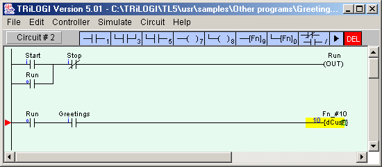
1) Create a ladder logic circuit, with an input contact named "Greetings", and use it to trigger a custom function #10 when the button connected to this input is pressed.
Note: Circuit #1 shown below is a standard ladder "seal" circuit which turns on the output "Run" whenever the input "Start" is closed momentarily. The "Run" output will only be turned OFF when the NC "Stop" input is energized. In Circuit #2, both the "Run" bit and "Greetings" input must be closed to trigger the Custom Function #10. The Custom Function #10 is "differentiated" (aka "one-shot") type which means that it will execute only once when triggered

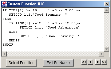
2) Next, edit the custom function #10 and enter the following TBASIC program code:

That's all ! Now compare what you need to do to achieve the same result with other programming languages. Pure BASIC may be fine, but handling a single bit input is not its best strength, and unless it has built-in LCD command you will be struggling to address the I/O ports that controls the 14 pins of the LCD display.
How about trying to do that with your traditional pure ladder logic code? First take out your thick programming manual and figure out how to store the ASCII codes for the messages in those obsure memory locations and two hours later you may or may not get it done!
Note: You only need to use the BASIC language as and when needed as demonstrated in the above case. Otherwise, the PLC will happily execute standard ladder logic circuit based on AND, OR, NOT, timers, counters only!
Still not convinced? Then download our TRiLOGI software with built-in simulator, create the above program and run it on your PC to verify the outcome. This software is used by thousands of college students for learning PLC programming. Almost everything can be simulated, including the LCD display and the real time clock.
Other Examples
The following demonstrate how easy it is to program in TBASIC language to achieve tasks that can be quite tedious or impossible in traditional Ladder PLCs.
| 1. Show Message on built-in LCD | 2. Read Analog Input |
| SETLCD
row, column, string
e.g. |
x
= ADC(n)
n
= 1 to 4 (the analog input channel #) |
| 3. Set Analog Output | 4. Set PWM Output |
| SETDAC
n, x n = 1 (D/A #1) x = output value 0 to 4096 e.g. SETDAC 1, (X+Y)/100 |
SETPWM
n, x, freq n = 1 or 2 (PWM Channel #) x = output value 0-10000 (0-100%) freq = frequency in Hz e.g. SETPWM 1, 2550, 10000 |
| 5. Run Stepper Motor | 6. Read Real Time Clock |
| STEPSPEED n, pps, acc n = 1 or 2 (Stepper controller channel) pps = Maximum pulses per second acc = acceleration steps to reach max pps. STEPMOVE
n, count, rly e.g. STEPSPEED
1, 5000, 100 |
The
PLC's Real-Time-Clock (RTC) derived date and time can be accessed via
variables DATE[1] to DATE[3] and TIME[1] to TIME[3], respectively.
e.g. IF DATE[4] > 5 THEN :ENDIF |